
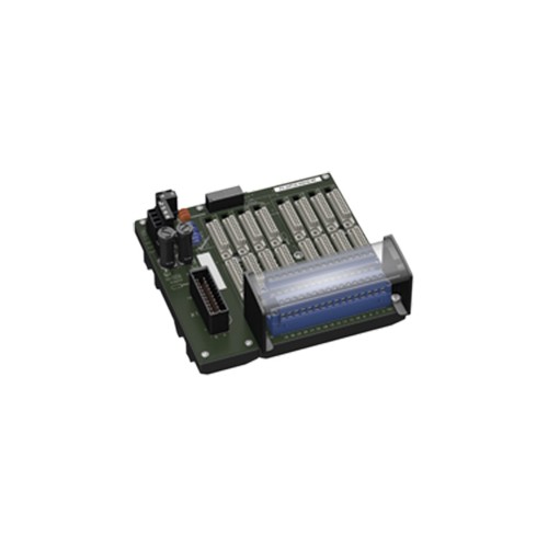
FC-GPCS-RIO16-PF Pepperl+Fuchs Termination Board
- Product Item: FC-GPCS-RIO16-PF
| Supply | ||
|---|---|---|
| Connection | TB3: terminals 2, 4(+); 1, 3(-) | |
| Nominal voltage | 24 V DC , in consideration of rated voltage of used isolators | |
| Voltage drop | 0.9 V , voltage drop across the series diode on the termination board must be considered | |
| Ripple | ≤ 10 % | |
| Fusing | 4 A , in each case for 16 modules | |
| Power dissipation | ≤ 500 mW , without modules | |
| Reverse polarity protection | yes | |
| Redundancy | ||
| Supply | Redundancy available. The supply for the isolators is decoupled, monitored and fused. | |
| Fault indication output | ||
| Connection | TB4: terminals 1, 2 | |
| Output type | volt-free contact | |
| Switch behaviour |
no fault: relay contact closed power supply fault: relay contact open |
|
| Contact loading | 30 V DC , 1 A | |
| Indicators/settings | ||
| Display elements |
LED Supply1 (power supply termination board), green LED LED Supply2 (power supply termination board), green LED LED Error Status (fault indication), red LED - LED lits: power supply fault |
|
| Directive conformity | ||
| Electromagnetic compatibility | ||
| Directive 2014/30/EU | EN 61326-1:2013 (industrial locations) | |
| Conformity | ||
| Electromagnetic compatibility |
NE 21:2017 For further information see system description. |
|
| Degree of protection | IEC 60529:2001 | |
| Ambient conditions | ||
| Ambient temperature | -20 ... 60 °C (-4 ... 140 °F) | |
| Storage temperature | -40 ... 70 °C (-40 ... 158 °F) | |
| Mechanical specifications | ||
| Degree of protection | IP20 | |
| Connection | ||
| Field side | explosion hazardous area: pluggable screw terminals , blue | |
| Control side | non-explosion hazardous area: 37-pin Sub-D connector | |
| Supply | pluggable screw terminals , black | |
| Fault output | pluggable screw terminals , black | |
| Core cross section | screw terminals: 0.25 ... 2.5 mm2 (24 ... 12 AWG) | |
| Material | housing: polycarbonate | |
| Mass | approx. 830 g | |
| Dimensions | 273 x 155 x 153 mm (10.7 x 6.1 x 6.0 inch) (W x H x D) , depth including module assembly | |
| Mounting | on 35 mm DIN mounting rail acc. to EN 60715:2001 | |
| Data for application in connection with hazardous areas | ||
| EU-type examination certificate | CESI 06 ATEX 022 | |
| Marking |
 II (1)G [Ex ia Ga] IIC II (1)D [Ex ia Da] IIIC I (M1) [Ex ia Ma] I II (1)G [Ex ia Ga] IIC II (1)D [Ex ia Da] IIIC I (M1) [Ex ia Ma] I
|
|
| Non-hazardous area | ||
| Maximum safe voltage | 250 V (Attention! Um is no rated voltage.) | |
| Certificate | DEMKO 18 ATEX 2116 X | |
| Marking |
II 3G Ex ec nC IIC T4 Gc
|
|
| Galvanic isolation | ||
| Field circuit/control circuit | safe electrical isolation acc. to IEC/EN 60079-11, voltage peak value 375 V | |
| Directive conformity | ||
| Directive 2014/34/EU | EN IEC 60079-0:2018+AC:2020 , EN 60079-7:2015+A1:2018 , EN 60079-11:2012 , EN 60079-15:2010 , EN 50303:2000 | |
| International approvals | ||
| UL approval | E106378 | |
| Control drawing | 116-0327 | |
| IECEx approval | ||
| IECEx certificate |
IECEx CES 06.0003 IECEx UL 18.0111 X |
|
| IECEx marking |
[Ex ia Ga] IIC [Ex ia Da] IIIC [Ex ia Ma] I Ex ec nC IIC T4 Gc |
|
| General information | ||
| Supplementary information | Observe the certificates, declarations of conformity, instruction manuals, and manuals where applicable. For information see www.pepperl-fuchs.com. | |
| System | Classcode |
|---|---|
| ECLASS 11.0 | 27210107 |
| ECLASS 10.0.1 | 27210107 |
| ECLASS 9.0 | 27210107 |
| ECLASS 8.0 | 27210107 |
| ECLASS 5.1 | 27210121 |
| ETIM 8.0 | EC001485 |
| ETIM 7.0 | EC001485 |
| ETIM 6.0 | EC001485 |
| ETIM 5.0 | EC001485 |
| UNSPSC 12.1 | 39121008 |


